Featured Summary
-
Identify Components: Familiarize yourself with the battery, controller, rear hub motor, throttle, brake cut-offs, and pedal-assist sensor (PAS) in your e-bike system.
-
Tools & Safety: Gather wire strippers, crimpers, a soldering iron, heat shrink, electrical tape, zip ties, and a multimeter. Always disconnect the battery and use a fuse on the battery’s positive lead for safety.
-
Battery to Controller: Connect the battery’s red positive wire to the controller’s + input and the black negative to –. Double-check polarity and include a main fuse or circuit breaker near the battery. Some controllers have a second thin red “ignition” wire that must also be tied into the positive to power on.
-
Motor Connections: Match and connect the three phase wires from the controller to the hub motor (usually yellow, green, blue). Plug in the motor’s hall sensor connector, aligning the 5 thin wires by color: red to red (+5V), black to black (ground), and blue/green/yellow signal wires.
-
Throttle & Sensors: Attach the throttle’s 3-pin connector (typically red, black, and a signal wire) to the controller. Connect brake cut-off switches (2-wire connectors) and the PAS sensor if available, matching any color-coded plugs. These are optional for basic function but add safety and assist features.
-
Secure & Test: Insulate all splices with heat-shrink tubing and secure loose wires with zip ties. Before applying full power, check all connections with a multimeter (no short between + and –). Then power on the system and do a test run with the wheel off the ground – the motor should spin smoothly when you twist the throttle, and cut off when brakes are applied. Troubleshoot any abnormal behavior (e.g. motor stuttering or not running) by rechecking wiring and connectors.
E-Bike Wiring Basics: Components and Connections
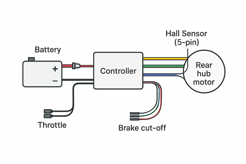
Understanding how each component connects is the first step in electric bike wiring. A typical e-bike with a rear hub motor has a central wiring harness that links all electrical parts.
Here are the key components and their wiring roles:
Battery
The battery (often 36V or 48V) supplies DC power. It connects to the controller via two heavy-gauge wires – red (+) and black (–). A fuse or circuit breaker is wired on the positive lead to protect against short circuits.
Controller
The controller is the “brain” that manages power flow to the motor and sensors. It has multiple connectors: a pair of thick power inputs from the battery, three phase outputs to the motor, and several smaller signal connectors for throttle, brakes, PAS, etc.
Many controllers also feature a thin ignition or power-switch wire (often a second red) that must be connected to battery positive for the controller to turn on.
Hub Motor
The rear hub motor is a brushless DC motor with two sets of wires coming out: three large phase wires that carry motor power, and a hall sensor bundle of five (or six) thinner wires.
The phase wires are typically color-coded yellow, green, and blue to match the controller’s outputs.
The hall sensor wires usually include red (5V supply), black (ground), and three colored signal wires (yellow, green, blue) that tell the controller the rotor position. (Some motors have an extra sensor wire, e.g. for speed, which can be left unconnected if the controller doesn’t use it.)
Throttle
Most throttles are thumb or twist grips with a 3-wire cable. The common color scheme is red for +5V input, black for ground, and another color (often green or yellow) for the throttle signal output. These plug into a matching 3-pin connector on the controller. (Some throttles include a fourth wire for an LED battery indicator or on/off switch.)
Brake Cut-Offs
E-brake levers have a pair of wires (often red and black or white) that connect to the controller’s brake input connectors. When you squeeze the brake, these wires either close or open a circuit that signals the controller to cut motor power. Each brake lever usually has its own 2-pin connector.
Pedal Assist Sensor (PAS)
The PAS typically uses a 3-wire connection (power, ground, signal) that plugs into the controller. It detects pedaling and allows the controller to provide assistance. Colors for PAS wires are not universal, but connectors are often keyed so you match the correct plug from the controller.

The table below summarizes the wiring harness connections, typical wire colors, and notes on each:
| Function | Typical Wire Colors | Notes (Connector Type) |
|---|---|---|
| Battery Positive (+) | Red (heavy gauge) | Main power from battery (Fuse on this line); connector e.g. XT60 |
| Battery Negative (–) | Black (heavy gauge) | Main ground from battery (common return); connector paired with positive (XT60/Anderson) |
| Motor Phase A/B/C | Yellow, Green, Blue (heavy) | 3-phase motor power wires (U/V/W); often bullet or similar connectors |
| Motor Hall Sensors | Red (+5V), Black (GND), Yellow, Green, Blue (thin) | 5-wire sensor plug (JST 6-pin) for motor position feedback; must align colors/pinout exactly |
| Throttle (Hall type) | Red (+5V), Black (GND), Green/Yellow (Signal) | 3-wire throttle connector (JST 3-pin); some models add a fourth wire (e.g. blue for LED) |
| Brake Cut-off Switch | Red & Black (per lever) | 2-wire connectors (usually open until brake is pressed); optional but recommended for safety |
| Pedal-Assist Sensor | Red (+5V), Black (GND), other (Signal) | 3-wire connector (often JST); color varies by brand (match connector from controller) |
Note: Color codes are mostly standardized, but always verify with your specific kit’s documentation. Some brands may use different color conventions or combined multi-pin harnesses. When colors differ between a motor and controller, identify the +5V and ground wires first (red and black), then match the remaining signal wires by process of elimination. The same principle applies to throttle and other sensors – ensure the supply and ground go to the correct pins, or you risk miswiring.
Preparation and Safety
Before diving into actually connecting wires, take time for planning and preparation. Good prep will make the wiring process smoother and prevent common issues.
Tool Checklist
Having the right tools and supplies on hand will save a lot of frustration. Here’s a checklist of useful tools for an eBike wiring project:
-
Wire cutters/strippers: For cutting cables to length and removing insulation cleanly.
-
Crimping tool and connectors: For attaching spade/bullet connectors or crimp terminals securely, especially on high-current wires.
-
Soldering iron and solder: Preferred for strong, low-resistance joins on critical wires (battery and motor phase wires). Soldering ensures a solid connection.
-
Heat shrink tubing: Various sizes to insulate and protect connections. Use heat shrink (or electrical tape, in a pinch) to cover all exposed joints.
-
Multimeter: Essential for checking voltage, continuity, and verifying that there are no short circuits before connecting the battery.
-
Miscellaneous: Screwdrivers, hex keys (to mount components), zip ties or cable wraps (for bundling wires neatly), and safety gear like insulated gloves and safety glasses.
Having these tools ready will make the wiring process safer and more reliable. For instance, a multimeter can verify the battery polarity and that +5V is present on throttle lines during testing, while heat shrink tubing ensures no bare metal is left exposed.
Safety Precautions
Working on an electric bike involves potentially high currents and sensitive electronics, so safety is paramount.
Always disconnect the battery or power source before working on any wiring. If your battery has an on/off switch, turn it off; better yet, remove the battery pack from the bike entirely while you wire everything.
Many controllers have large capacitors that can hold a charge even after disconnecting the battery – press the bike’s power button or wait a few minutes to ensure any stored charge is drained.
It’s highly recommended to install a fuse or circuit breaker on the battery’s positive lead if one isn’t already present.
A fuse located close to the battery will blow and protect the system if a short or overload occurs, rather than allowing wires to overheat. Choose a fuse rated slightly above your system’s maximum current (for example, a 30A fuse for a 25A controller).
When stripping and joining wires, make sure no stray wire strands are left that could short to other wires or the bike’s frame.
Use proper insulation (heat shrink or quality electrical tape) on every connection. Route cables away from moving parts (like wheels, chain, or pedals) and avoid pinching them with screws or sharp frame edges.
It’s a good practice to leave some slack in wires going to the handlebars (throttle, display) to accommodate steering without tension.
Finally, never work on wiring while the bike is powered. Double-check polarity (red to +, black to –) at every battery or power connection before turning power on. Taking these precautions will prevent the most common hazards like blown components, sparks, or even electrical fires.
Step-by-Step Wiring Guide
Now that you have an overview and your tools, let’s get into connecting everything. This step-by-step guide takes you through rewiring an electric bike with a rear hub motor, assuming you have all the components (motor, controller, battery, etc.) ready. Even if your kit or bike differs slightly, the general process remains the same.
Step 1: Plan Your Layout
Before making any actual connections, plan where each component will sit on your ebike and how the wires will run. Sketch a simple diagram or at least mentally map the layout.
Key points to consider:
Component Placement
Decide where to mount the controller (often under the downtube or behind the seatpost), battery (in the frame triangle or a rear rack), and run the motor cable along the frame to the controller. Ensure the motor’s cable, which comes out of the rear hub axle, can reach the controller location without stretching.
Cable Routing
Plan a path for the wires that avoids moving parts and sharp edges. Typically, wires follow the frame tubes. For a rear hub motor, you might route its cable along the chainstay and up the seat tube or downtube to the controller. Leave slack at the handlebar for steering and at any suspension points so wires won’t tension when the bike moves.
Label If Needed
If your wiring bundle has many similar connectors, label them with tape (e.g., tag which connector is for the throttle vs. the brake) to avoid confusion later. This is especially useful if colors are not perfectly matched or if you have extra unused connectors. As an expert tip, marking wires now will simplify any future troubleshooting or upgrades.
Ensure at this stage that you have all necessary connectors or adapters. For example, if your new controller’s plugs don’t match the motor or throttle connectors, you might need to splice wires or use adapter cables. It’s better to identify those needs upfront during planning rather than mid-way through wiring.
Step 2: Mount the Components
Secure the major components on the bike before connecting the wires. Mounting everything first will make it easier to measure wire lengths and secure them properly:
Mount the Controller
Use the provided bracket or zip ties to attach the controller to the frame.
Common spots are under the downtube, on the seat tube, or on a rear rack. The location should have some ventilation (controllers can get warm) and be relatively protected from water and debris.
Make sure the connector ends of the controller’s wiring harness are accessible for plugging in the other components.
Mount the Battery
If it’s a removable battery pack with a holder, install the holder on the frame (usually on the down tube’s bottle cage mounts or a rear rack). Ensure it’s locked in place and secure.
If it’s a DIY battery, use strong straps or brackets. The battery should be stable and not rattle. Position it such that its output wires (or connector) can reach the controller’s input leads without strain.
Other Parts
Install the throttle on the handlebar (if not already in place) and the PAS sensor near the crank (if your kit includes one).
Attach brake levers with built-in cut-off switches if you are replacing the originals. Run the throttle cable and any sensor cables along the frame towards the controller, loosely securing them for now.
Basically, get every piece physically in place where it needs to be on the bike.
By mounting first, you’ll know exactly how long each wire needs to be and can avoid having excess slack or, worse, a wire that’s too short to reach its connector.
Step 3: Connect the Battery to the Controller
Now, connect the battery to the controller’s power inputs. This is the high-current connection, so take care to do it correctly:
Identify the battery leads and controller leads
The battery will have a positive (+) and negative (–) lead or plug. The controller typically has a red wire (or a red connector lead) for + and a black wire for – coming out among its cables.
If your controller uses connectors, they might be pre-fitted (for instance, an XT60 or Anderson plug for the battery). If the connectors on the battery and controller already match, simply plug them together after ensuring the polarity is correct. Red should go to red, black to black.
If connectors don’t match
Often, DIY enthusiasts will solder or crimp matching connectors. You can cut off mismatched plugs and join the wires directly: connect red battery wire to red controller wire, and black to black.
Use a solid connection method – ideally solder the wires and cover with heat shrink tubing. If soldering isn’t available, use a high-current crimp connector or a mechanical connector like a wire nut (as a temporary measure) and insulate thoroughly.
Insert a fuse
If not already present in your battery pack, add an inline fuse or circuit breaker on the positive lead between the battery and controller.
For example, use an inline fuse holder and choose a fuse slightly above your controller’s max amp draw. This fuse will blow if something is wired incorrectly or if there’s a short, potentially saving your controller and wiring from damage.
Connect the ignition wire (if applicable)
As mentioned, some controllers have a small red “ignition” or “power lock” wire in addition to the main red power cable. This wire needs to be connected to battery positive as well (often spliced into the main red, or connected to a keyswitch which then connects to battery +).
If you miss this, the controller might not power on at all. Tie it in now (following your controller manual instructions).
Double-check this battery-to-controller connection. verify that positive is indeed going to positive, and negative to negative. A reverse polarity connection here can instantly fry your controller or battery BMS.
Use the multimeter to confirm voltage on the controller side once connected (with the battery on, you should see battery voltage on the controller’s power input). Do not turn the system on yet beyond checking with a meter.
We will test fully after all wiring is done.
Step 4: Connect the Motor Phases and Hall Sensors
Next, hook up the rear hub motor’s wires to the controller. There are two parts to this: the three phase wires that carry high power to the motor, and the multi-wire hall sensor connector for motor feedback.
Phase wires
These are the three thicker wires coming from the motor, usually colored Yellow, Green, and Blue. The controller will have three wires (or sockets) with corresponding colors. Connect yellow→yellow, green→green, blue→blue.
If your motor or controller uses different color coding or lacks labels, consult documentation; however, most follow this scheme.
Each phase wire pair should be securely joined – if your kit has bullet connectors, plug them in fully (ensure a tight fit).
If you had to cut wires, solder or crimp each pair and insulate it. It’s important these connections are solid because they carry high current; a loose phase wire can cause sputtering or melted connectors under load.
Hall sensor connector
The hall sensor is typically a single plug with 5 or 6 small wires. If your controller and motor come as a set, they likely have matching plugs that only fit one way – simply align the arrows or keys and connect them.
If you had to manually connect these, match the colors: red on motor to red on controller (5V supply), black to black (ground), and the three remaining colors (often blue, green, yellow) each to their counterpart.
Some controllers or motors use white for an extra sensor (speed or temperature); if one side has a wire for it and the other doesn’t, leave the extra wire unconnected.
Color mismatch scenario
If your motor and controller have different color wires on the hall connector (this can happen when mixing brands), identify the red and black first (they are usually clearly marked or can be found with a multimeter: red will have +5V from controller, black is ground).
Connect those accordingly.
Then for the three signal wires, you may need to try combinations if colors don’t directly correspond. Typically, you’d connect based on position if the connector plugs in, or if you have individual pins, try matching one color and swap if the motor doesn’t run correctly (more on troubleshooting this later).
Once phase and hall connections are made, secure the motor cable along the frame. Use clamps or zip ties to fix the cable to the chainstay and up towards the controller so it won’t snag on anything.
There’s usually a grommet or stress relief near the motor axle – ensure that is properly seated to protect the wires where they exit the motor.
Step 5: Connect the Throttle and Other Controls
With the heavy wiring done, connect the low-voltage controls and sensors to the controller. Most of these will be plug-and-play if your kit is uniform, using matching connectors. Common connections include:
Throttle
Plug in the throttle’s three-pin connector to the controller’s throttle input. Usually this is a JST-SM 3-pin plug or similar. Ensure it’s fully seated.
The throttle connector from the controller might be labeled or color-coded (red, black, green/yellow). If the connectors were cut, you’ll splice the wires: red from controller to throttle’s red, black to black, and the remaining color from controller to the throttle signal wire.
Double-check the throttle wiring – connecting it incorrectly (e.g. swapping ground and signal) can cause either no response or erratic behavior.
Brake cut-off switches
Connect each brake lever’s cable to the controller’s corresponding 2-pin connector (often labeled as “E-brake” or similar).
The wires are typically red and black on both sides, but the connector is not polarized (whichever way you plug it is fine, since it’s just opening/closing a circuit).
If you only have one brake sensor, connect that one and leave the other brake connector unused (or install a second sensor later).
If connectors don’t match, you can splice the two wires from the brake lever to the two wires of the controller’s brake input – since it’s just a switch, it doesn’t matter which wire connects to which as long as they form a circuit.
Remember, these are optional for functionality, but highly recommended for safety: they allow the controller to cut power when you brake.
PAS sensor
If your bike has a pedal assist sensor, plug its connector into the controller (often a 3-pin or 5-pin connector).
Many PAS use a 3-pin connector (red, black, and another color for signal). Ensure it goes into the correct plug (check the controller manual for the PAS label). A mismatched PAS connection might prevent assist from working but won’t typically affect throttle operation.
If your system doesn’t have PAS, or you choose not to install it, you can leave this connector empty – the bike will still run with throttle only.
Display or other accessories
Some kits include an LCD display panel or other accessories (horn, lights, etc.) that have dedicated connectors. Connect these as instructed by the kit manual.
Displays usually use a multi-pin connector that branches off the controller harness. Make sure to screw on or firmly press any waterproof connectors (like Higo connectors common on many kits) until fully engaged.
At this point, every device should be plugged into the controller: battery, motor (phase + hall), throttle, brakes, PAS, and any other optional devices. Do a once-over check that no connector is forgotten or half-connected.
Step 6: Verify Connections and Secure Wiring
Before you apply power, it’s crucial to verify all connections and tidy up the wiring harness:
Continuity and polarity check
Use your multimeter to ensure there are no unintended shorts. With the battery disconnected, check continuity between the main + and – leads on the controller; there should be no continuity (any beep indicates a short that must be fixed before proceeding).
If you have a pre-charge resistor or antilock switch, make sure it’s not confusing the reading. Also verify continuity on each individual connection you made (for example, tug gently on soldered joints to ensure they’re solid). Confirm that positive wires only connect to corresponding positive points, etc.
Tighten connectors
If your system uses screw terminals or bolts (some batteries use screw clamps, and some controllers have screw-down terminals for power), ensure those are tight. Loose electrical connections can cause heat buildup.
For plug connectors, make sure they are fully seated and locked. A partially connected hall sensor plug, for instance, might cause the motor to stutter.
Insulate and secure
All spliced joints should now be covered with heat shrink tubing (preferred) or at least several layers of electrical tape. There should be no exposed copper visible.
Use zip ties to bundle wires neatly along the frame and near the controller. Create service loops or slack where appropriate (at joints or connectors) so that stress is not on the connection itself.
Check that steering the handlebar from side to side doesn’t stretch any cables, and that the suspension travel (if any) isn’t pulling wires. A clean wiring job not only looks professional but also reduces the chances of wires snagging or breaking from movement.
Take a final moment to cross-check every connector with your wiring diagram or the table above. It can help to have a checklist (battery ✅, phase wires ✅, halls ✅, throttle ✅, etc.) and tick them off. This methodical verification can catch things like a forgotten ignition wire or a PAS plugged into the wrong port before any damage is done.
Step 7: Initial Power-On Test
With everything connected and verified, it’s time to power up and test the system. Elevate the rear wheel off the ground using a bike stand or by propping the bike securely, since the motor may spin unexpectedly during testing. Then proceed with these tests:
Power on
Reconnect the battery and turn on the battery switch if it has one. Many controllers or displays will show an LED or initialization sequence when powered.
If nothing happens at all (no lights on the display or controller LED), re-check the battery connection and the controller’s power wires (including the ignition wire). Assuming it powers on, continue.
Throttle test
Gently twist the throttle while observing the rear wheel. It should begin to spin smoothly up to speed. Try this slowly at first – if the wheel jerks or sputters (cogging), or only vibrates without spinning, immediately release the throttle.
Jerky motion could indicate the phase and hall wires are mis-matched (we’ll address troubleshooting in the next section). If the wheel spins but in the wrong direction (bike tries to go backward), you can fix that by swapping any two of the three phase wires (after powering off). This will reverse the rotation direction.
Brake cut-off test
While the wheel is spinning via throttle, squeeze one of the brake levers. The motor should cut out (wheel slows to a stop). Release the brake and the throttle should resume control. Test both brake levers.
If engaging a brake does not cut power, check that the brake sensor wires are correctly connected.
If the motor never spins and always acts as if a brake is pressed (some controllers won’t allow throttle if they think brakes are on), you may have a brake sensor wired incorrectly or a faulty brake switch that is stuck closed. Disconnect the brake connectors and test the throttle again to isolate the issue.
PAS test (if applicable)
If you installed a pedal assist sensor, test it by turning the cranks (while the bike is still securely supported).
Typically, you need to turn on the PAS function via a display or ensure the controller is in PAS mode. The motor should engage after a revolution or two of the pedals. If it doesn’t, double-check the PAS alignment and wiring, but remember some controllers require the display to be set to a PAS level above 0. This can vary, so consult your specific system’s procedure.
General observation
Listen for any unusual noises from the motor. A smooth hum is normal, but grinding or clicking is not – that could indicate a wiring issue like a bad hall sensor connection.
Also, monitor if any wires are getting warm during this short test. Warmth on phase wires under no load could mean a poor connection.
If all tests pass, congratulations – you’ve successfully wired your e-bike hub motor system! If something is amiss, don’t worry. The next section will help troubleshoot common wiring problems that might arise during the testing phase.
Ensuring Compatibility Across Different Kits
One challenge in wiring or rewiring an e-bike is that different kits and brands might have slight variations. However, most DIY electric bike systems share the same basic principles.
Here’s how to keep your wiring universally applicable across common setups, including 36V vs 48V systems and various connector types.
36V vs 48V Systems (and Other Voltages)
E-bike components are typically designed for a specific voltage range, but from a wiring perspective a 36V system is wired almost identically to a 48V system.
The difference lies in the battery and controller ratings, not in how you hook up the wires. For example, a 36V battery has a nominal voltage around 36 volts, whereas a 48V battery is around 48 volts – yet both will have a pair of output wires (positive and negative) that connect to a controller in the same manner.
The controller-to-motor wiring (phase and hall), throttle, brake sensors, and PAS – all of these use the same connectors and color codes regardless of voltage.
That said, you must ensure that all your components are compatible with the voltage you are using.
A 36V controller paired with a 48V battery, for instance, could be dangerous or simply not function properly (the higher voltage might damage 36V capacitors or the system might refuse to start due to over-voltage). Conversely, a 48V controller on a 36V battery may not turn on because the voltage is too low for its defaults, or it might work but the bike will have less power.
Always match your battery and controller voltage ratings. The hub motor itself is usually less sensitive – a 48V-rated motor will run on 36V (with reduced speed and power), and a 36V motor can often run on 48V (with more speed, but potentially more heat). However, exceeding voltage ratings can shorten motor lifespan, so stick to intended values for long-term reliability.
In summary, follow the same wiring steps for 36V, 48V, or even higher voltage kits – just be vigilant that each component (especially the controller and battery) is suitable for that voltage. The wire gauges used might differ: higher power (often associated with higher voltage) setups use thicker wires to handle current, but the connection points remain alike.
Connectors and Color Code Variations
Different e-bike manufacturers and conversion kits may use different connector types, but they all serve to link the same groups of wires. Many generic kits stick to a color-coded system and common connector types that make it easy to plug everything in. For instance:
Battery connectors
Common standards are yellow XT60 or larger XT90 plugs, Anderson Powerpole connectors (often red/black paired), or proprietary connectors for higher-end systems.
As long as positive and negative are correctly connected, the type of connector doesn’t change the wiring. You can always adapt or swap connectors if needed.
Motor phase connectors
Many hub motors and controllers use bullet connectors (3.5mm or 4mm bullets, often gold-colored) for the three phase wires.
Others might use a single molded plug for all phase wires, but internally those are just three separate connections.
If your motor and controller phase connectors don’t match, you can either replace one side’s connectors to match the other or remove them and directly splice the wires color-to-color.
Hall sensor and other signal connectors
A lot of kits use JST-SM or JST-Multi plugs (small white or red plastic connectors) for hall sensors, throttles, brakes, and PAS.
These are usually keyed so you can’t plug them in wrong if they match. Branded systems (like Bosch, Shimano, Bafang mid-drives) often use Higo or Rosenberger circular connectors which are waterproof and keyed.
If mixing components (say a generic controller with a motor that has a different plug), you may need to do some custom adapter wiring. It often involves identifying each of the wires by function and matching them up.
Remember that color codes are usually consistent (e.g. red to red, blue to blue), but not always, so use diagrams when available.

When dealing with connector differences, the key tips are:
(1) maintain correct polarity for power connections,
(2) match each function wire (don’t mix up throttle vs brake connectors, for example),
(3) if unsure, consult the wiring diagram or manual of the components.
It’s often possible to find documentation or forum posts for generic controller wiring color codes. In the end, even with different physical plugs, an ebike controller wiring harness will always have a way to attach to a battery, motor, throttle, and sensors. By focusing on the function of each wire and not just the color, you can adapt any kit to any bike.
Common Wiring Mistakes and Troubleshooting
Even with careful work, it’s possible to encounter issues when you first run your rewired e-bike. Don’t panic – most problems come down to a few common wiring mistakes.
Below we outline some typical issues and how to troubleshoot them. The approach is to verify each subsystem (battery, controller, motor, throttle, sensors) one by one.
No Power or No Motor Response
Symptom: Nothing happens when you turn on the system or twist the throttle – no wheel movement, and possibly no lights on the display or controller. Possible causes & fixes:
Battery or main power not connected properly
Verify the battery is charged and turned on. Check the main fuse; if it blew, the system will be dead (replace the fuse after finding the cause). Ensure the battery’s connectors are fully plugged in and polarity is correct. A completely loose or disconnected battery will obviously result in no power.
Controller ignition wire not connected
If your controller requires linking a thin ignition wire to battery positive, make sure that’s done.
A forgotten ignition wire is a very common oversight that results in a “dead” bike. If unsure, look for an extra red (or sometimes orange) wire on the controller aside from the thick red power lead.
That should either connect to your battery’s switch or be tied into the battery’s red wire to feed the controller’s internal power.
Faulty or loose connections
Check the battery connector for any loose pins or wires (for example, Anderson connectors can sometimes push out of their housing). Also ensure the controller’s ground connection (black wires) is solid – a broken ground will open the circuit. Tighten any screw terminals on the battery or controller.
Throttle not getting voltage
If the bike powers on (maybe an LED lights up) but the motor won’t go when you throttle, it could be the throttle isn’t wired correctly.
Use a multimeter to check the throttle’s voltage line: you should see ~5V between red and black at the throttle connector when the system is on.
If 5V is missing, the controller isn’t powering the throttle – possibly a broken wire or mis-plugged connector. If 5V is present, check the throttle signal wire: it should vary from ~1V to ~4V as you twist the throttle.
No change on throttle signal could mean the throttle itself is faulty or wired wrong.
Motor or hall connector unplugged
Another simple one – if the motor’s hall sensor plug isn’t fully seated, the controller might not allow the motor to turn.
Some controllers can run sensorless (still spin the motor without hall sensors) but many will just do nothing if the hall connector is disconnected. Make sure the hall plug is secure. Likewise, a completely unplugged phase wire (one of the three) might result in no movement at all or very jerky movement. Check that all three phase wires are connected.
Next steps: Once you correct the above, try again. If the display comes on and you can read battery voltage but the motor still won’t respond to throttle, consider if any safety interlock is active.
Many e-bikes won’t start the motor if the brake is detected as engaged – a miswired brake cutoff could inadvertently signal a constant brake. Try disconnecting the brake sensors entirely and test the throttle again.
If the motor now works, you’ve found the issue (see the brake section below).
Motor Stutters or Runs Rough
Symptom: When you apply throttle, the motor twitches, stutters, or makes grinding/cogging noises and doesn’t spin properly. It may jiggle back and forth or turn very slowly with a growl.
This usually points to a phase/hall synchronization issue – the controller isn’t getting the correct signals from the motor hall sensors relative to the phase power sequence.
Possible causes & fixes:
Hall sensor wires mis-matched
Even if colors were matched, there’s a chance that the hall wiring order is wrong (this can happen if using a controller and motor from different sources that use different color conventions). The result is the controller firing the phases out-of-sync with the motor’s position.
Double-check that the hall connector is fully plugged and that each wire goes to its corresponding partner. If your hall wires colors don’t match one-to-one, you might need to find the correct combination by trial.
One method: keep the phase wires in correct color order, and try swapping the positions of the three hall sensor signal wires until the motor runs smoothly. There are 6 combinations, but often just moving each one step (rotating the trio) can align the signals.
Phase wires not matched or loose
Similarly, if one of the phase wires is connected to the wrong controller output, the motor will jerk. Ensure yellow from motor goes to yellow on controller, etc. (Note: on some systems, two of the three can be swapped to reverse direction, but if all three are jumbled it won’t run right at all.)
Also check the physical connectors – a phase bullet connector that isn’t fully seated or a cold solder joint can cause intermittent contact, leading to stuttering under load.
Damaged hall sensor or running sensorless
If one of the hall sensors in the motor is dead (or the hall cable is damaged), the motor might cog at low speed and only run smoothly if you manage to get it to high speed (this is a behavior of sensorless operation).
As a diagnostic, some controllers have a “self-learn” or sensorless mode – consult your manual. But in a DIY scenario, if halls are suspect, you might measure each hall output with a voltmeter while slowly rotating the wheel (each should toggle between 0 and 5V).
A faulty hall sensor will stay at one voltage. Replacing a hall sensor is advanced, but knowing this can point you to the issue.
In summary, 90% of stuttering issues come from wiring order mismatches. Take a systematic approach: verify or swap wires one at a time and test.
It’s a bit of trial and error if documentation isn’t available. The good news is that once you hit the right combination, the motor will run silky smooth. When correctly wired, the motor should start from a stop with no shuddering.
If it only runs rough under load (rider on it), that could be a weak connection or too thin wires causing voltage drop – ensure your phase wires and battery cables are thick enough for the current.
Motor Spins Without Throttle Input
Symptom: As soon as you turn on the system (or at least as soon as you enable the motor), it starts running at full or partial speed without you twisting the throttle. This can be startling but is a clear sign of a miswiring.
Possible causes & fixes:
Throttle wires shorted or crossed
The most likely cause is that the throttle signal is being held high due to incorrect wiring.
If the throttle’s 5V and signal wires are swapped, for instance, the controller might see a full 5V on the signal line at all times – interpreting that as if you’re demanding full throttle.
Re-examine the throttle connector wiring . Ensure the colors are correctly matched: red (5V) to red, black (ground) to black, and signal to signal. If you accidentally connected the throttle’s signal wire to 5V, the motor would indeed run as if at full throttle all the time.
A quick test: disconnect the throttle connector entirely. If the motor stops spinning on its own, the issue is with the throttle or its wiring. You might have to repin the connector or correct the splices.
Shorted throttle cable
Sometimes a damaged throttle cable can short internally (for example, the 5V and signal lines touching). Inspect the throttle cable along its length for cuts or pinch points. Also check inside the throttle itself if accessible – wires to the hall sensor in the throttle might have come loose. Replacing the throttle with a spare (if available) can quickly tell if the throttle unit is the problem.
Cruise control or PAS confusion
Some controllers have a “cruise” function or weird default if PAS is active.
If your controller is expecting a PAS and you have it connected incorrectly, it might interpret a signal as a constant pedal input. Ensure PAS wires are right, or disconnect PAS during initial testing if unsure.
Similarly, check if there is a cruise control wire (often a loop or button). If a cruise control connector is accidentally shorted, the controller might lock on throttle. Disconnect any unknown accessory connectors (often a pair of wires that might be looped for limiting speed or engaging cruise).
Once you identify the cause, the fix is usually straightforward – correct the wiring or replace the faulty part. Running away of the motor is scary, but fortunately it’s usually due to low-voltage signal issues (throttle wires), not an indication of a high-power fault.
Blown Fuse or Short Circuit (Sparks/Smoke)
Symptom: When you connect the battery or try to run the motor, the main fuse blows immediately, or you see sparks/smoke from a connector or wire. This indicates a direct short or severe wiring error in the high-power circuit.
Possible causes & fixes:
Battery polarity reversed
The most dangerous mistake is accidentally connecting the battery backwards into the controller (positive to negative). Many controllers lack reverse-polarity protection, so this often results in instant destruction of components (smoke, blown capacitors) or a violent spark as the connectors touch.
If you suspect this happened, immediately disconnect and inspect the controller for damage. To avoid this, always double-check polarity with a voltmeter before connecting.
The red wire on controller must go to battery +. If you did reverse it and the fuse blew, count yourself lucky – the fuse likely saved the controller. Replace the fuse and correct the wiring.
Short circuit in wiring
A pinched power cable or an exposed bit of conductor touching the frame can cause a short.
Inspect the battery leads and phase wires for any cuts or crushed sections. It might be that when you secured the controller, a screw went through a wire (it happens!). If a fuse blows immediately upon connecting the battery, something is creating a path between + and –.
Use the multimeter in continuity mode between + and – of the controller input (with battery disconnected) – if it beeps, there’s a short in the wiring or inside the controller.
You may have to isolate by unplugging components: disconnect the motor phase and hall connectors and test again; if the short goes away, the issue might be in the motor wiring (e.g., a phase wire shorted to another or to the motor case). If the short remains with motor unplugged, it could be inside the controller or in the throttle/brake wiring.
Overcurrent on start
If the fuse blows only when you hit the throttle (not immediately at power-on), it could be that the fuse rating is too low for the surge current, or the controller is faulty and drawing too much.
For instance, a 20A fuse on a controller that draws 25A will likely blow under full throttle. Ensure your fuse is appropriately sized – typically slightly above the controller’s max current spec (e.g., use 40A fuse for a 35A controller).
If sized correctly, blowing fuses under throttle likely indicates a short in the motor (phase wires shorted together or to ground) or a blown controller MOSFET that is shorted internally. At that point, further troubleshooting would involve component replacement.
Whenever you blow a fuse or see smoke, stop and investigate. Do not repeatedly replace fuses and brute-force it – you’ll risk more damage. The cause must be found.
The fuse did its job by protecting the rest of the system, so find the short or miswire that caused it. A common oversight is leaving a stray strand of copper from a wire crimp that bridges to another terminal – these tiny culprits can blow fuses quickly, so examine your connections closely (a magnifying glass helps).
Brake Cut-Off Misbehavior
Symptom: The motor cuts out unexpectedly or won’t run at all unless certain wires are disconnected, often traced to the brake cut-off circuit. If the controller constantly thinks a brake is activated, it will ignore throttle input to prevent motoring against brakes.
Possible causes & fixes:
Brake sensor wired incorrectly
If the brake connectors were spliced manually, ensure that each brake lever’s two wires go to the two wires of the controller’s brake input.
If you accidentally tied one brake wire to ground or 5V, it could permanently signal a brake. The brake input on controllers is usually a closed circuit = motor enabled, open circuit = brake active (or vice versa on some).
Check your controller manual: some expect the two brake wires to be connected (closed) when no brake is pressed and open when brake is pressed, while others send 5V out on one line and expect it back on the other when not braking.
In either case, a miswire can simulate a brake. The safest test is to unplug or disconnect the brake switch wires entirely – the controller should then see “no brake”. If the motor now runs, rewire the brake switches according to proper pairing.
Stuck or faulty brake switch
Physically ensure your brake levers’ sensors are not stuck. Some use little magnets and sensors; if a magnet fell off or is misaligned, the sensor might always read as “brake on.”
If you suspect this, try the bike with one brake connected at a time to identify which brake is causing the issue. Replace or adjust that sensor as needed.
Electronic lock or alarm systems
In some e-bikes, there are extra wires for things like an electronic lock or alarm that can also immobilize the motor.
If your controller has such features and you’re not using them as intended, make sure those wires are in the correct state (often an alarm wire needs to be tied or left floating for the bike to run).
This is less common, but worth mentioning if you have unexplained behavior even after the basics are sorted.
Brake cut-off issues are usually resolved by either disconnecting the brakes for troubleshooting or carefully re-doing those connections. It’s worth the effort, since you do want functioning cut-offs.
Once fixed, test again: the motor should only run when no brake is pressed, and stop the instant you pull a brake lever.
Advanced Tips and Best Practices
With the wiring now functional, you can further improve the durability and serviceability of your e-bike’s electrical system. The following expert tips will help elevate your wiring job from just working to robust and easy to maintain.
Label and Document Everything
It might seem tedious, but labeling your wires and keeping notes pays off in the long run. Use small pieces of colored tape or heat shrink tubing with labels on key connectors (especially if you have many similar connectors).
For example, label the throttle connector vs. the PAS connector if they are both 3-pin and could be confused. Label battery leads, especially if you have to disconnect them often.
In addition, take clear photos of all your connections or draw a wiring diagram specific to your bike. Document the wire colors and where they go, especially if you deviated from standard color coding when adapting connectors.
Having your own “wire map” will simplify troubleshooting months or years later, or if you upgrade a component. It’s much easier to recall which accessory a loose connector is for when it’s labeled.
Consult manufacturer schematics when available and save those too. Many controllers come with a wiring diagram – keep that in a folder or digitally.
In community forums, people often share pinouts for generic controllers; bookmarking or printing these can be a lifesaver if you need to reconnect something down the line.
In short, treat your wiring like documentation for a project: future-you (or the next owner) will thank you for the clear labels and diagrams.
Weatherproof Your Connections
Electric bikes often face the elements, and water or corrosion is the enemy of electrical connections. Even if your bike is not intended for rainy rides, it’s wise to protect the wiring:
Use waterproof connectors
If possible, use connectors with rubber seals (like Higo connectors) for exposed areas.
If your kit didn’t come with them, you can at least apply dielectric grease inside connectors to repel moisture. For critical joints (battery, phase wires), consider adding a layer of self-fusing silicone tape around the connector after plugging it in, to seal out water.
Conformal coating and sealing
For the controller, ensure its casing is properly closed. Some enthusiasts go as far as applying a conformal coating to the controller’s circuit board to protect against moisture (this is an advanced step and should be done only if you’re familiar, since it involves opening the controller).
At minimum, tuck the controller in a spot on the bike that’s shielded from direct splashes. Mount it with connectors facing downward if possible, so water runs away from the openings.
Corrosion prevention
If you ride in wet conditions or near salt (e.g., winter roads), periodically disconnect and inspect connectors for signs of corrosion (green or white crusty deposits).
Spraying a moisture displacer like WD-40 (sparingly) or applying dielectric grease can help. Ensure any drain holes in motor hubs or controller casings are not clogged, so condensation doesn’t accumulate. Using heat shrink with adhesive (marine grade) on splices can also keep moisture out of the wire strands themselves.
By weatherproofing, you’ll prevent random issues that occur when water bridges contacts or corrodes the metal. Dry connections and protected wires mean your e-bike will perform reliably in all seasons.
Routine Maintenance Checks
After putting some miles on your e-bike, include the wiring in your regular maintenance checklist. Vibrations and flexing can loosen connections over time:
Periodic inspection
Every so often (perhaps every 100-200 miles or after rough rides), inspect visible wiring for any wear. Look for places where cables might be rubbing the frame or have shifted dangerously close to moving parts. Add additional zip ties or re-route as needed to prevent abrasion.
Check insulation
Especially at the head tube (due to steering) or rear swingarm (if full suspension), the wire insulation can wear if not properly constrained. Ensure no copper is exposed. If you find a worn spot, fix it immediately with tape or by replacing that section of wire.
Re-tighten terminals
If your battery or controller uses screw terminals or ring lugs (common on higher power setups), check that those haven’t vibrated loose. A loose main power connection can lead to arcing (which will char connectors) or intermittent power cuts. Make sure the fuse holder (if any) is snug and the fuse itself is not corroded.
Clean and lubricate connectors
Unplugging and replugging connectors occasionally can wipe the contacts and ensure they stay relatively oxidation-free. For connectors exposed to dirt, a quick shot of electrical contact cleaner can remove gunk. After cleaning, applying a tiny bit of dielectric grease on connector pins can fend off corrosion and ease plugging/unplugging.
Taking five minutes for wiring maintenance every now and then can prevent a roadside failure. Most wiring problems give warning signs (flickering power, intermittency) before total failure – if you notice anything like that, don’t ignore it. A quick fix of a frayed wire at home is far better than getting stranded.
Future Upgrades: Higher Power or Voltage
If you plan to upgrade your e-bike’s performance later – say moving from a 36V to 48V battery, or swapping the motor for a more powerful one – your wiring will likely need an upgrade too. Higher power means more current, and possibly different connectors:
Wire gauge
Higher current draw (amperage) requires thicker wires to avoid overheating. For example, if you move up to a 1500W system at 48V (~30A), you’ll want at least 12 AWG or 10 AWG for the phase and battery wires (the stock 14 AWG might get too hot).
Always size wires for the maximum current plus a safety margin.
Fuse and controller settings
If upping the battery voltage, ensure the controller’s capacitors and MOSFETs can handle it. The low-voltage cutoff (LVC) on the controller may need changing (often by reprogramming or swapping a resistor) if, for instance, you use a 52V battery on a 48V controller – otherwise the battery could over-discharge.
As for the fuse, a higher wattage system will pull more amps, so use an appropriate fuse (e.g., going from a 20A system to a 35A system, upgrade a 30A fuse to maybe 40A). Never bypass or “over-fuse” a circuit beyond what the wires can handle; it’s better for a fuse to blow than a wire to melt.
Connector upgrades
At higher currents, small connectors might overheat. Many DIY builders move to automotive style connectors or higher-rated ones (for instance, an XT90 or Anderson SB50 for battery instead of an XT60).
Phase wire bullets can be upgraded to 5mm or 6mm types for more contact area. Ensure any upgrade maintains correct polarity and secure connection.
Motor and controller compatibility
Wiring a new motor to an old controller (or vice versa) follows the same process you’ve learned, but do check if the new components have any extra wires (some high-power motors have temperature sensors – usually two extra wires – that you might incorporate to a compatible controller for thermal rollback).
If not used, cap them off safely. When increasing voltage, remember that the motor’s speed will increase roughly proportional to voltage, so be prepared for that. As long as you keep the wiring solid, the main concern becomes whether the motor can handle the extra speed/heat.
Always approach upgrades cautiously – incremental changes and tests are wise. If you go to a much higher power, consider rewiring the hub motor internally with thicker phase leads (some enthusiasts do this for sustained high currents).
That’s an expert project on its own, but the principle is the same: avoid wires as the bottleneck. If you plan to increase voltage or current significantly (e.g. moving to a 72V battery or a 45A controller), upsizing your fuse and wire gauge is critical. It might also be time for a more robust controller that uses thicker gauge wires by default.
Conclusion
Rewiring an electric bike with a rear hub motor can seem daunting, but as this guide shows, it breaks down into manageable steps.
By understanding each component and following best practices, you’ve essentially become the electrician for your own DIY electric bike. To explore complete models ready to ride, check out our electric bikes. From making solid battery connections with the correct polarity to neatly routing a wiring harness that can withstand the bumps of the road, you’ve created a safe and reliable system. Always remember that patience and attention to detail are your best tools.
Happy riding, and stay charged!


2 thoughts on “How to Wire or Rewire a Rear Hub Motor Electric Bike”
Martk Lucidi
This is incredibly helpful for first-time DIYers like me—and likely for experienced e-bike mechanics as well. It streamlines the entire project by surfacing contingencies early and eliminating doubt about overlooked details. I especially appreciated the section on the motor aviation connector; before finding this article, that issue alone cost me sleep. I look forward to the day when most e-bike components are fully universal.
Frank Steele
great article thanks for making it posting it 🥂 cheers